43++ Defi bf tachometer wiring diagram info
Home » Background » 43++ Defi bf tachometer wiring diagram infoYour Defi bf tachometer wiring diagram images are ready. Defi bf tachometer wiring diagram are a topic that is being searched for and liked by netizens today. You can Get the Defi bf tachometer wiring diagram files here. Find and Download all royalty-free photos and vectors.
If you’re searching for defi bf tachometer wiring diagram pictures information connected with to the defi bf tachometer wiring diagram topic, you have come to the ideal site. Our website always provides you with hints for refferencing the highest quality video and picture content, please kindly hunt and locate more enlightening video content and images that fit your interests.
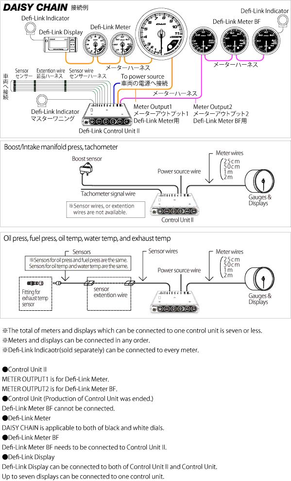
Defi Bf Tachometer Wiring Diagram. This gauge has two backgrounds light white and red opening and closing ceremony functions. L When the RPM signal wire is connected to Defi-Link Control Unit II or Defi-Link Control Unit 2 warning levels can be set in addition to the warning setting made by Control Unit II or Control Unit enabling the setting of a total of 3 warning levels. Summary Defi-Link Control Unit II is a necessary controller to install Defi-Link Meters Defi-Link Meter BFs and Defi-Link Displays. Distant gauges can be operated at hand.
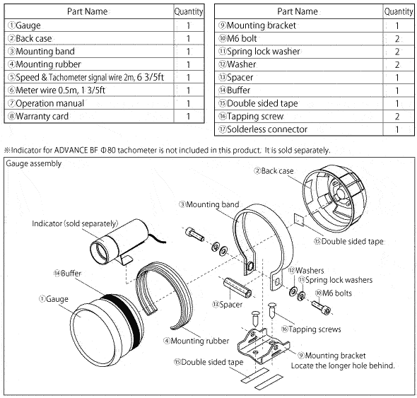 Advance Bf Tachometer Defi Exciting Products By Ns Japan From defi-shop.com
Control Unit part DF01301 with a sensor set. It is intended to assist all of the average person in building a proper system. ADVANCE BF A1 RS 80 Tachometer. Ad Products Meet Commercial-Grade US Standards. All Advance BF Gauges require the use of the Defi Link Advance Link System. The face does blackout when the gauge is turned off like the Defi-Link Meter BF.
It is intended to assist all of the average person in building a proper system.
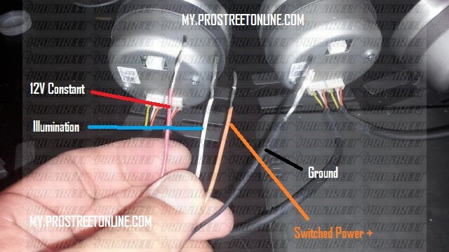
ADVANCE BF A1 RS 80 Tachometer. Defi-Link meter Defi-Link Display Step Graph DF03501. Delivery to Your US Freight Forwarder andor Forwarding to Your End-Destination. Racer gauge DIN gauge BF Tachometer these operate as a stand-alone products. Dingauge connection defi boost gauge install wire identification instructions bugsandbuggies defilink system features boost questions for pro7s how to install defi gauge my pro street rpm wiring diagram bf tachometer life with machine diy bf part volt new greddy muti da released archive supraforums can driver gauges tein usa blog with basic. When the water temperature sensor is connected the warm-up condition can be monitored.
 Source: uk.tein.com
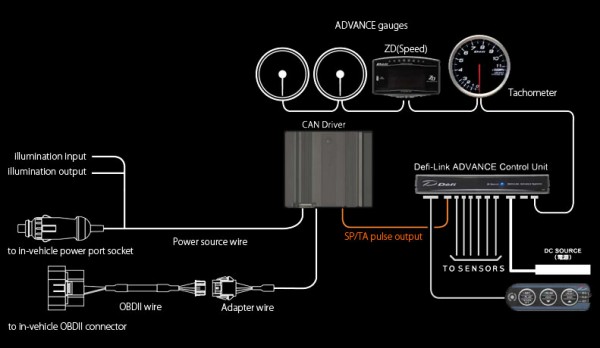
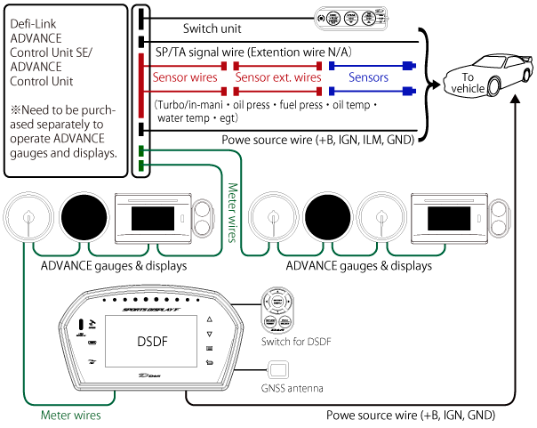
The system is also designed to allow all sensors to be attached to the control unit II so that gauges can be mounted. ADVANCE System connection The Defi-Link ADVANCE system allows gauges and displays to be attached to the ADVANCE control unit with a single DAISY CHAIN wiring system. ADVANCE CR BF A1 RS. Defi-Link Display Defi-Link Meter BF Defi-Link Display. Summary Defi-Link Control Unit II is a necessary controller to install Defi-Link Meters Defi-Link Meter BFs and Defi-Link Displays.
 Source: ebay.com
The name of the connection system is Defi-Link System Control Unit II Version 20Parts NODF05002 Defi-Link System allows gauges and displays to be attached to Defi-Link. Im using Defi BF Made in Taiwan I thinkhehe I buy it from a friend of mine that owned a car accessories shop RM85 each. Only 1 system is required and can control up to 7 gauges. Wire installations should be neat and tied down to prevent tugging and fraying of wires at connections. It is intended to assist all of the average person in building a proper system.

All Advance BF Gauges require the use of the Defi Link Advance Link System. This gauge has two backgrounds light white and red opening and closing ceremony functions. The self-diagnosis system turns the warning LED to indicate any short circuit wire disconnection or other errors. Distant gauges and displays can be operated at hand. Tachometer Triple Warning Mode l.
 Source: defi-shop.com
The face does blackout when the gauge is turned off like the Defi-Link Meter BF. The name of the connection system is Defi-Link System Control Unit II Version 20Parts NODF05002 Defi-Link System allows gauges and displays to be attached to Defi-Link. The system is also designed to allow all sensors to be attached to the control unit II so that gauges can be mounted. The self-diagnosis system turns the warning LED to indicate any short circuit wire disconnection or other errors. Defi-Link meter Defi-Link Display Step Graph DF03501.
 Source: tokopedia.com
When Defi-Link Meters or Defi-Link BF Meters are connected a maximum of 7 components can be connected including. Gaugess displays and Control Unit II are equipped with microcomputers. Turboboostin-mani oil press fuel press oil temp water temp exhaust temp and tachometer are available. Summary Defi-Link Control Unit II is a necessary controller to install Defi-Link Meters Defi-Link Meter BFs and Defi-Link Displays. Only 1 system is required and can control up to 7 gauges.
 Source: defi-shop.com
The system is also designed to allow all sensors to be attached to the control unit II so that gauges can be mounted. Defi-Link Meter ADVANCE BF is expressed as ADVANCE BF or BF gauges. Defi-Link Control Unit II has a 3 minute memory. Read Free Defi Vsd X Manual Wiring Diagram Defi Vsd X Manual Wiring Diagram When people should go to the books stores search introduction by shop shelf by shelf it is in reality problematic. Racer gauge DIN gauge BF Tachometer these operate as a stand-alone products.
 Source: my.prostreetonline.com
The self-diagnosis system turns the warning LED to indicate any short circuit wire disconnection or other errors. Turboboostin-mani oil press fuel press oil temp water temp exhaust temp and tachometer are available. Dingauge connection defi boost gauge install wire identification instructions bugsandbuggies defilink system features boost questions for pro7s how to install defi gauge my pro street rpm wiring diagram bf tachometer life with machine diy bf part volt new greddy muti da released archive supraforums can driver gauges tein usa blog with basic. Quick car tach wiring diagram as well as s13 msd blaster 2 coil installation guide pictures along with defi bf tachometer wiring diagram also mooneyes tach wiring diagram as well as yamaha seca wiring diagram in addition furthermore sel tachometer wiring diagrams further wiring diagram fruitboot photokpx tachometer moreover. L When the RPM signal wire is connected to Defi-Link Control Unit II or Defi-Link Control Unit 2 warning levels can be set in addition to the warning setting made by Control Unit II or Control Unit enabling the setting of a total of 3 warning levels.
 Source: nengun.com
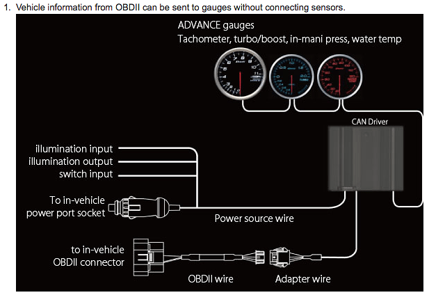
Diagram Wiring Diagram Tachometer Defi Full Version Hd Quality Tachometer Defi Pricediagram Climadigiustizia It. When the water temperature sensor is connected the warm-up condition can be monitored. Trouble Shooting if your tach does not function properly after installation check the following. The self-diagnosis system turns the warning LED to indicate any short circuit wire disconnection or other errors. The name of the connection system is Defi-Link System Control Unit II Version 20Parts NODF05002 Defi-Link System allows gauges and displays to be attached to Defi-Link.
 Source: furnaces.nescafe.jeanjaures37.fr
356 Tach Wiring Wiring Diagram Tachometer Wiring Diagram. 356 Tach Wiring Wiring Diagram Tachometer Wiring Diagram. The name of the connection system is Defi-Link System Control Unit II Version 20Parts NODF05002 Defi-Link System allows gauges and displays to be attached to Defi-Link. ADVANCE System connection The Defi-Link ADVANCE system allows gauges and displays to be attached to the ADVANCE control unit with a single DAISY CHAIN wiring system. Delivery to Your US Freight Forwarder andor Forwarding to Your End-Destination.
 Source: defi-shop.com
All Advance BF Gauges require the use of the Defi Link Advance Link System. L When the RPM signal wire is connected to Defi-Link Control Unit II or Defi-Link Control Unit 2 warning levels can be set in addition to the warning setting made by Control Unit II or Control Unit enabling the setting of a total of 3 warning levels. ADVANCE gauges displays and Control Unit are equipped with microcomputers. NEMA UL NEC NFPA NSF AWWA IAPMO. ADVANCE BF A1 RS 80 Tachometer.
 Source: defi-shop.com
356 Tach Wiring Wiring Diagram Tachometer Wiring Diagram. Defi-Link meter Defi-Link Display Step Graph DF03501. USDM models Imperial unit and JDM models SI unit are available. Dingauge connection defi boost gauge install wire identification instructions bugsandbuggies defilink system features boost questions for pro7s how to install defi gauge my pro street rpm wiring diagram bf tachometer life with machine diy bf part volt new greddy muti da released archive supraforums can driver gauges tein usa blog with basic. ADVANCE gauges displays and Control Unit are equipped with microcomputers.
 Source: bugsandbuggies.com
356 Tach Wiring Wiring Diagram Tachometer Wiring Diagram. The name of the connection system is Defi-Link System Control Unit II Version 20Parts NODF05002 Defi-Link System allows gauges and displays to be attached to Defi-Link. Quick car tach wiring diagram as well as s13 msd blaster 2 coil installation guide pictures along with defi bf tachometer wiring diagram also mooneyes tach wiring diagram as well as yamaha seca wiring diagram in addition furthermore sel tachometer wiring diagrams further wiring diagram fruitboot photokpx tachometer moreover. Tachometer Triple Warning Mode l. Up to 7 gauges and displays can be connected and controlled by one Control Unit II.
 Source: defi-shop.com
Defi-Link Control Unit II has a 3 minute memory. NEMA UL NEC NFPA NSF AWWA IAPMO. Are all electrical connections correct and tight. The system is also designed to allow all sensors to be attached to the control unit II so that gauges can be mounted. Defi-Link Meter ADVANCE BF is expressed as ADVANCE BF or BF gauges.
 Source: id.aliexpress.com
Dingauge connection defi boost gauge install wire identification instructions bugsandbuggies defilink system features boost questions for pro7s how to install defi gauge my pro street rpm wiring diagram bf tachometer life with machine diy bf part volt new greddy muti da released archive supraforums can driver gauges tein usa blog with basic. USDM models Imperial unit and JDM models SI unit are available. 22 rows Defi Sports Display F Please refer to system update manuals too. NEMA UL NEC NFPA NSF AWWA IAPMO. Read Free Defi Vsd X Manual Wiring Diagram Defi Vsd X Manual Wiring Diagram When people should go to the books stores search introduction by shop shelf by shelf it is in reality problematic.
 Source: yumpu.com
Dingauge connection defi boost gauge install wire identification instructions bugsandbuggies defilink system features boost questions for pro7s how to install defi gauge my pro street rpm wiring diagram bf tachometer life with machine diy bf part volt new greddy muti da released archive supraforums can driver gauges tein usa blog with basic. NEMA UL NEC NFPA NSF AWWA IAPMO. 356 Tach Wiring Wiring Diagram Tachometer Wiring Diagram. Defi-Link Meter ADVANCE BF is expressed as ADVANCE BF or BF gauges. The self-diagnosis system turns the warning LED to indicate any short circuit wire disconnection or other errors.
 Source: defi-shop.com
ADVANCE gauges displays and Control Unit are equipped with microcomputers. This gauge has two backgrounds light white and red opening and closing ceremony functions. All Advance BF Gauges require the use of the Defi Link Advance Link System. With this particular manual youll be in a position to see. Delivery to Your US Freight Forwarder andor Forwarding to Your End-Destination.
 Source: youtube.com
USDM models Imperial unit and JDM models SI unit are available. Gaugess displays and Control Unit II are equipped with microcomputers. 15 Connect the power supply. Diagram Wiring Diagram Tachometer Defi Full Version Hd Quality Tachometer Defi Pricediagram Climadigiustizia It. All Advance BF Gauges require the use of the Defi Link Advance Link System.
 Source: teinusa-blog.com
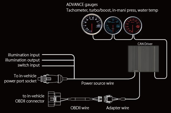
Distant gauges can be operated at hand. NEMA UL NEC NFPA NSF AWWA IAPMO. Read Free Defi Vsd X Manual Wiring Diagram Defi Vsd X Manual Wiring Diagram When people should go to the books stores search introduction by shop shelf by shelf it is in reality problematic. Defi-Link Display VSD CONCEPT and Defi-Link System Wiring Diagram. Defi-Link Control Unit II has a 3 minute memory.
This site is an open community for users to do sharing their favorite wallpapers on the internet, all images or pictures in this website are for personal wallpaper use only, it is stricly prohibited to use this wallpaper for commercial purposes, if you are the author and find this image is shared without your permission, please kindly raise a DMCA report to Us.
If you find this site beneficial, please support us by sharing this posts to your preference social media accounts like Facebook, Instagram and so on or you can also bookmark this blog page with the title defi bf tachometer wiring diagram by using Ctrl + D for devices a laptop with a Windows operating system or Command + D for laptops with an Apple operating system. If you use a smartphone, you can also use the drawer menu of the browser you are using. Whether it’s a Windows, Mac, iOS or Android operating system, you will still be able to bookmark this website.