38+ Danfoss vlt 2800 wiring diagram info
Home » Wallpapers » 38+ Danfoss vlt 2800 wiring diagram infoYour Danfoss vlt 2800 wiring diagram images are available in this site. Danfoss vlt 2800 wiring diagram are a topic that is being searched for and liked by netizens today. You can Download the Danfoss vlt 2800 wiring diagram files here. Download all royalty-free images.
If you’re searching for danfoss vlt 2800 wiring diagram pictures information linked to the danfoss vlt 2800 wiring diagram interest, you have visit the ideal site. Our website always gives you hints for refferencing the highest quality video and image content, please kindly search and find more enlightening video articles and images that fit your interests.
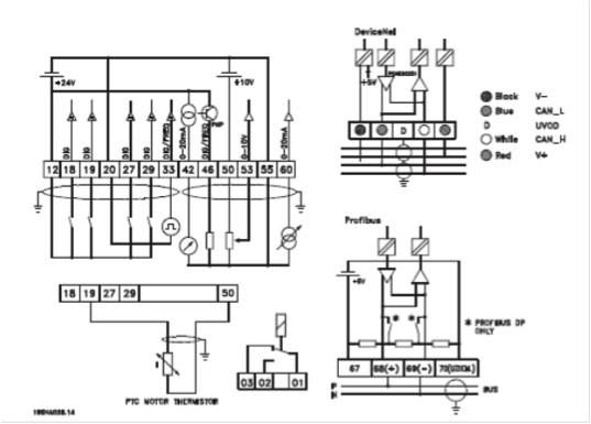
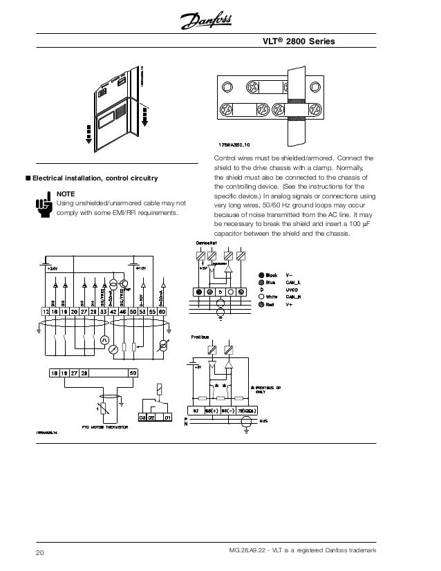
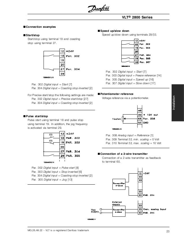
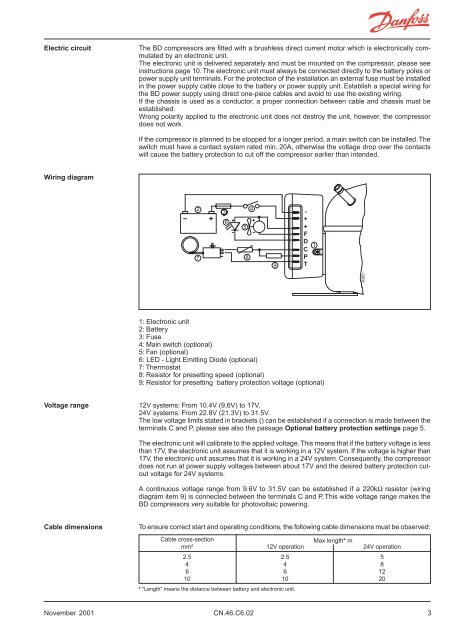
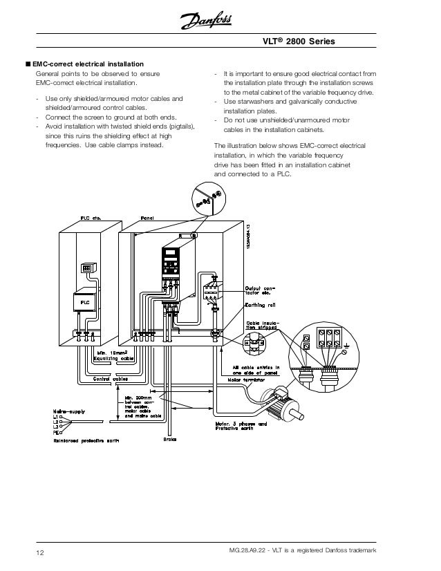
Danfoss Vlt 2800 Wiring Diagram. Or maximum output current I in accordance with the VLT 2800 has a pulse pattern in which it is possible to set diagram in Illustration 53. Primary Wiring Diagram 2001 Ford Windstar Ignition Coil. VLT 2800 Series 10 MG27A222 - VLT is a registered Danfoss trademark. Diagrams below Figure A and B.
 مهندس محمدیان 09132211861 تعمیرات اینورتر اینورتور درایو 3vf Vvvf Vfd Vsd Abb Acs350 Wiring Diagram تعمیر درای Circuit Diagram Inverter Ac Circuit From pinterest.com
VLT is a registered trademark. Danfoss VLT 2800 Series Manuals Manuals and User Guides for Danfoss VLT 2800 Series. VLT 2800 frequency converters allow side-by-side inst allation on a wall in any position as the units. When reading through this Operating Instructions you will come across various symbols that require special. Startstop of motor is to be done with the switch. Full part number is - VLT2815PS2B20SBR1DBF00A00C1 131Z9199 Download the Danfoss VLT Manual from the.
2x These Operating Instructions can be used with all cascade controller options with software version 2x.
Vlt 6000 hvac 8000 aqua danfoss vfd control wiring diagram 03 operating instructions drive design guide sw3 2x refrigeration fc 103 automationdrive 300 0 102 0x technical data Instruction Manual Cascade Controller Option Vlt 6000 Hvac 8000 Aqua Pdf Free Danfoss Vfd Control Wiring Diagram 03 Taurus Interior Fuse Bathroom Vents Gotoscool Jeanjaures37 Fr. 44 Wiring Schematic 12 45 Access 14 46 Motor Connection 14 47 AC Mains Connection 15 48 Control Wiring 16 481 Control Terminal Types 16. 12 Available Documentation Documentation is available to understand specific frequency converter functions and programming. Danfoss Vlt 2800 Wiring Diagram line and components AC line transformer wires fuses and The Danfoss VLT controls both the amplitude and the. Startstop of motor is to be done with the switch. Cummins N14 Celect Wiring Diagram.

This number can be found on the red nameplate on the outside left side of the drive. VLT is a registered Danfoss trademark5 General The specific installation instructions may vary depending upon the model of VLT 6000 Series being installed. 2x These Operating Instructions can be used with all cascade controller options with software version 2x. NOTE With the IP 21 solution all units require a minimum of 4 in air on each side. This Design Guide can be used for all VLT Series frequency converters with contact Danfoss Drives for further infor- 6 wires out of motor Delta con-.
 Source: manualzz.com
VLT 2800 Quick Guide VLT 2800 Design Guide VLT 2800 Filter Instruction Brake Resistor Manual Profibus DP V1 Manual Profibus DP Manual VLT 2800 DeviceNet Manual. Means of a min. Unit has been obsoleted replaced by Midi FC 280. Primary Wiring Diagram 2001 Ford Windstar Ignition Coil. Danfoss Vlt 2800 Wiring Diagram line and components AC line transformer wires fuses and The Danfoss VLT controls both the amplitude and the.

NOTE With the IP 21 solution all units require a minimum of 4 in air on each side. When reading through this Operating Instructions you will come across various symbols that require special. 2x These Operating Instructions can be used with all cascade controller options with software version 2x. EN 55011 Class A1. VLT is a registered Danfoss trademark5 General The specific installation instructions may vary depending upon the model of VLT 6000 Series being installed.
 Source: durham.co.th
10mm² Cu or an addtional PE wire - with the same cable cross section as the Mains wiring - must be terminated separately. General Information Manual Operating Instructions Manual Quick Manual Instruction Manual Quick Setup. About Danfoss Contact us Home page. Danfoss VLT. All VLT 2800 units can be installed side-by-side and in any position as the units do not require ventilation on the side.
 Source: pinterest.com
Danfoss VLT 2800 Series Manuals Manuals and User Guides for Danfoss VLT 2800 Series. 10mm² Cu or an addtional PE wire - with the same cable cross section as the Mains wiring - must be terminated separately. The Danfoss Randall way WC4B Wiring Centre suited to most popular wiring connection information covers most popular domestic heating control systems. Startstop of motor is to be done with the switch. Danfoss Vlt 2800 Wiring Diagram wiring diagram is a simplified suitable pictorial representation of an electrical circuitIt shows the components of the circuit as simplified shapes and the talent and signal associates in the midst of the devices.
 Source: fdocuments.in
Danfoss Vlt 2800 Wiring Diagram wiring diagram is a simplified suitable pictorial representation of an electrical circuitIt shows the components of the circuit as simplified shapes and the talent and signal associates in the midst of the devices. VLT 2800 frequency converters allow side-by-side inst allation on a wall in any position as the units. VLT 6000 HVAC and VLT 8000 AQUA Operating Instructions Software version. This number can be found on the red nameplate on the outside left side of the drive. 10mm² Cu or an addtional PE wire - with the same cable cross section as the Mains wiring - must be terminated separately.
 Source: slideshare.net
VLT 2800 frequency converters allow side-by-side inst allation on a wall in any position as the units. 2x These Operating Instructions can be used with all cascade controller options with software version 2x. When this occurs the model can be identified by a VLT Type 6XXX number. Cummins N14 Celect Wiring Diagram. 10mm² Cu or an addtional PE wire - with the same cable cross section as the Mains wiring - must be terminated separately.
 Source: pinterest.com
Downloads Follow our global channels Keep me updated. General Information Manual Operating Instructions Manual Quick Manual Instruction Manual Quick Setup. Danfoss VLT. Total wiring length to connect up to 10 VLT 6000 and VLT 2800 For BACLink portals ordered without an enclosure mount the unit drives from the BACLink portal should not exceed 3000 feet in an enclosed panel using the mounting holes provided on the 900m at 9600 baud rate. VLT 2800 Quick Guide 1 Quick Guide.
 Source: fliphtml5.com
VLT is a registered trademark. This Design Guide can be used for all VLT Series frequency converters with contact Danfoss Drives for further infor- 6 wires out of motor Delta con-. All VLT 2800 units can be installed side-by-side and in any position as the units do not require ventilation on the side. Please contact Danfoss regarding PELV. Primary Wiring Diagram 2001 Ford Windstar Ignition Coil.
 Source: jualplcomron.blogspot.com
44 Wiring Schematic 12 45 Access 14 46 Motor Connection 14 47 AC Mains Connection 15 48 Control Wiring 16 481 Control Terminal Types 16. RS-485 2W Terminal Diagram 1 Diagram 6 Diagram 1 cMT Series cMT3151 eMT Series eMT3070 eMT3105 eMT3120 eMT3150 HMI PLC COM1 COM3 RS485 2W RS485 2W Terminal 9P Male RS485 2W 9P Male Data- 1 6 69 Data- Data 2 9 68 Data GND 5 5 Diagram 2 cMT Series cMT-SVR cMT-G01 cMT-G02 cMT-HDM cMT-FHD. Startstop of motor is to be done with the switch. Downloads Follow our global channels Keep me updated. Setup will guide you through EMC correct installation of the frequency converter by connecting power motor and control wiring fig.
 Source: pinterest.com
Danfoss VLT. Danfoss VLT 2800 Series Manuals Manuals and User Guides for Danfoss VLT 2800 Series. 44 Wiring Schematic 12 45 Access 14 46 Motor Connection 14 47 AC Mains Connection 15 48 Control Wiring 16 481 Control Terminal Types 16. Vlt 6000 hvac 8000 aqua danfoss vfd control wiring diagram 03 operating instructions drive design guide sw3 2x refrigeration fc 103 automationdrive 300 0 102 0x technical data Instruction Manual Cascade Controller Option Vlt 6000 Hvac 8000 Aqua Pdf Free Danfoss Vfd Control Wiring Diagram 03 Taurus Interior Fuse Bathroom Vents Gotoscool Jeanjaures37 Fr. 2x These Operating Instructions can be used with all cascade controller options with software version 2x.
 Source: pinterest.com
Danfoss VLT. NOTE With the IP 21 solution all units require a minimum of 4 in air on each side. VLT 6000 HVAC and VLT 8000 AQUA Operating Instructions Software version. Primary Wiring Diagram 2001 Ford Windstar Ignition Coil. Danfoss Vlt 2800 Wiring Diagram line and components AC line transformer wires fuses and The Danfoss VLT controls both the amplitude and the.
 Source: slideshare.net
When reading through this Operating Instructions you will come across various symbols that require special. VLT is a registered Danfoss trademark5 General The specific installation instructions may vary depending upon the model of VLT 6000 Series being installed. We have 7 Danfoss VLT 2800 Series manuals available for free PDF download. VLT 2800 frequency converters allow side-by-side inst allation on a wall in any position as the units. Setup will guide you through EMC correct installation of the frequency converter by connecting power motor and control wiring fig.
 Source: pinterest.com
Primary Wiring Diagram 2001 Ford Windstar Ignition Coil. Danfoss Vlt 2800 Wiring Diagram wiring diagram is a simplified suitable pictorial representation of an electrical circuitIt shows the components of the circuit as simplified shapes and the talent and signal associates in the midst of the devices. EN 55011 Class A1. This Design Guide can be used for all VLT Series frequency converters with contact Danfoss Drives for further infor- 6 wires out of motor Delta con-. MG51A802 - VLT is a registered Danfoss trademark 5.

Primary Wiring Diagram 2001 Ford Windstar Ignition Coil. This Design Guide can be used for all VLT Series frequency converters with contact Danfoss Drives for further infor- 6 wires out of motor Delta con-. 44 Wiring Schematic 12 45 Access 14 46 Motor Connection 14 47 AC Mains Connection 15 48 Control Wiring 16 481 Control Terminal Types 16. Vlt 6000 hvac 8000 aqua danfoss vfd control wiring diagram 03 operating instructions drive design guide sw3 2x refrigeration fc 103 automationdrive 300 0 102 0x technical data Instruction Manual Cascade Controller Option Vlt 6000 Hvac 8000 Aqua Pdf Free Danfoss Vfd Control Wiring Diagram 03 Taurus Interior Fuse Bathroom Vents Gotoscool Jeanjaures37 Fr. Danfoss VLT.
 Source: slideshare.net
VLT 6000 HVAC and VLT 8000 AQUA Operating Instructions Software version. Or maximum output current I in accordance with the VLT 2800 has a pulse pattern in which it is possible to set diagram in Illustration 53. VLT is a registered trademark. All VLT 2800 units can be installed side-by-side and in any position as the units do not require ventilation on the side. VLT 2800 Quick Guide VLT 2800 Design Guide VLT 2800 Filter Instruction Brake Resistor Manual Profibus DP V1 Manual Profibus DP Manual VLT 2800 DeviceNet Manual.
 Source: yumpu.com
This number can be found on the red nameplate on the outside left side of the drive. NOTE With the IP 21 solution all units require a minimum of 4 in air on each side. Startstop of motor is to be done with the switch. The software version can be seen from parameter 624. This means that side-by-side mounting is not allowed.
 Source: slideshare.net
7111 Fixed Variable Speed Pump Wiring Diagram 127 7112 Lead Pump Alternation Wiring Diagram 127 7113 Cascade Controller Wiring Diagram 128 7114 StartStop Conditions 129 8 Installation and Set-up 130 81 Installation and Set-up 130. Danfoss VLT Inverter Drive from the 2800 Range. NOTE With the IP 21 solution all units require a minimum of 4 in air on each side. Total wiring length to connect up to 10 VLT 6000 and VLT 2800 For BACLink portals ordered without an enclosure mount the unit drives from the BACLink portal should not exceed 3000 feet in an enclosed panel using the mounting holes provided on the 900m at 9600 baud rate. RS-485 2W Terminal Diagram 1 Diagram 6 Diagram 1 cMT Series cMT3151 eMT Series eMT3070 eMT3105 eMT3120 eMT3150 HMI PLC COM1 COM3 RS485 2W RS485 2W Terminal 9P Male RS485 2W 9P Male Data- 1 6 69 Data- Data 2 9 68 Data GND 5 5 Diagram 2 cMT Series cMT-SVR cMT-G01 cMT-G02 cMT-HDM cMT-FHD.
This site is an open community for users to submit their favorite wallpapers on the internet, all images or pictures in this website are for personal wallpaper use only, it is stricly prohibited to use this wallpaper for commercial purposes, if you are the author and find this image is shared without your permission, please kindly raise a DMCA report to Us.
If you find this site helpful, please support us by sharing this posts to your preference social media accounts like Facebook, Instagram and so on or you can also save this blog page with the title danfoss vlt 2800 wiring diagram by using Ctrl + D for devices a laptop with a Windows operating system or Command + D for laptops with an Apple operating system. If you use a smartphone, you can also use the drawer menu of the browser you are using. Whether it’s a Windows, Mac, iOS or Android operating system, you will still be able to bookmark this website.