38++ Danfoss vfd with bypass wiring diagram information
Home » Wallpapers » 38++ Danfoss vfd with bypass wiring diagram informationYour Danfoss vfd with bypass wiring diagram images are ready in this website. Danfoss vfd with bypass wiring diagram are a topic that is being searched for and liked by netizens now. You can Find and Download the Danfoss vfd with bypass wiring diagram files here. Get all royalty-free vectors.
If you’re searching for danfoss vfd with bypass wiring diagram pictures information connected with to the danfoss vfd with bypass wiring diagram topic, you have come to the ideal blog. Our site frequently gives you suggestions for downloading the maximum quality video and picture content, please kindly surf and locate more informative video articles and graphics that fit your interests.
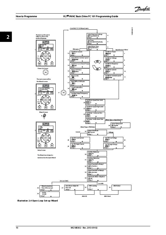
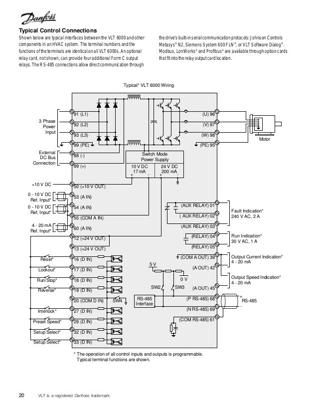
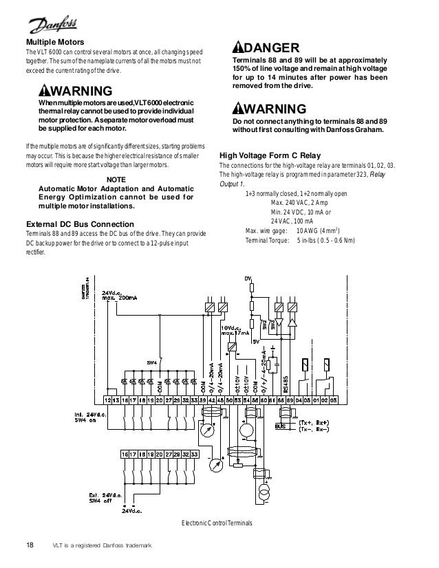
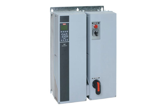
Danfoss Vfd With Bypass Wiring Diagram. Recently a customer asked about a way to tell remotely if a Danfoss VFD was in bypass- there are probably several ways to do this but here are a couple methods. Vfd Control Wiring Diagram Vfd Wiring Schematic Schema Wiring Diagram Preview. There are other types of bypasses in the market but the most common type of VFD bypass is the three-contactor bypass type. Bypass modeWhen bypass mode is selected the M3 contactor closes and allows the motor to run directly from the input line power.
 Danfoss Blog Incontrol From incontrolhvac.com
Wire the EMCS point to X56 56 On 3-contactor bypass drives ask us WHY we recommend and sell 3-co. Recently a customer asked about a way to tell remotely if a Danfoss VFD was in bypass- there are probably several ways to do this but here are a couple methods. This mode opens all contactors removing any power to the motor. Standard bypassnon bypass panel is to allow switching between VFD control and running in bypass. Vfd is a short form of variable frequency drive or variable voltage variable frequency driveThe VFDs are working based on changing the input frequency and input voltage of the motor we can change the speed of the. Danfoss Vfd Wiring Diagram Wiring Diagram Data Schema Pioneer avic n1 wiring diagram.
Condensate water pump Boiler DM demineralized water pump firefighting Jacky pump and all emergency pumps.
Vfd Control Wiring Diagram Vfd Wiring Schematic Schema Wiring Diagram Preview. Wire the EMCS point to X56 56 On 3-contactor bypass drives ask us WHY we recommend and sell 3-co. Danfoss mobile apps software and PC tools empower your VFD. Danfoss VFD Common StartStop. 15 Block Diagram of the Frequency Converter Illustration 11 is a block diagram of the frequency converters internal components. The reason that you would.
 Source: dodyjm.losdol2.jeanjaures37.fr
Danfoss Vfd Wiring Diagram Wiring Diagram Data Schema Pioneer avic n1 wiring diagram. Vfd is a short form of variable frequency drive or variable voltage variable frequency driveThe VFDs are working based on changing the input frequency and input voltage of the motor we can change the speed of the. LXTX thermostat wiring diagrams. Wiring diagram of the danfoss inverter optyma controller and pump down vlt 3500 manual hsa3 2006 cp715si to allow mc 024 110 unable connect in service motorised valve help please remove 103 timer 6 0 vfd relay delay settings gmc c5500. We need a good back up in order to avoid breakdown or stoppage of our industry.
 Source: wiringdiagramall.blogspot.com
Danfoss Vlt 6000 Bypass Wiring Diagram October 19 2019 1 Margaret Byrd. VFD Start Stop Wiring Diagram. Danfoss Vlt 6000 Bypass Wiring Diagram October 19 2019 1 Margaret Byrd. Recently a customer asked about a way to tell remotely if a Danfoss VFD was in bypass- there are probably several ways to do this but here are a couple methods. This design includes the standard Danfoss performance and features.
 Source: slideshare.net
Monitoring danfoss vfd in bypass october 04. Non-UL fuses 200 V to 480 V. Automatic bypass operation selectable and programmable including adjustable time delay. Option panel instruction manual. LXTX thermostat wiring diagrams.
 Source: slideshare.net
WARNING EQUIPMENT HAZARD Contact with rotating shafts and electrical equipment can result in death or serious injury. The VFD needs to also be checked for proper rotation when in bypass operation. Danfoss mobile apps software and PC tools empower your VFD. Danfoss vfd with bypass wiring diagram. Typical wiring diagram for any LX Thermostat.
 Source: ropye.sarc.mentra.tial.spon.vira.mohammedshrine.org
Below is the factory authorized method that Deppmann uses on the VFD with the three-contactor bypass. Danfoss mobile apps software and PC tools empower your VFD. I am here with giving you a VFD start stop wiring diagram for running a VFD through panel board push button and keypad of the VFD It is called HMI. This design includes the standard Danfoss performance and features. 15 Block Diagram of the Frequency Converter Illustration 11 is a block diagram of the frequency converters internal components.
 Source: viiintage.fuses-boxs.genericocialis.it
Vfd Control Wiring Diagram wiring diagram is a simplified all right pictorial representation of an electrical circuit. Ground wire of at least 10 mm2 6 AWG. Danfoss Vfd Wiring Diagram Wiring Diagram Data Schema Pioneer avic n1 wiring diagram. See table 12 for their functions. Two types of bypass options are available.
 Source: incontrolhvac.com
Wiring diagram of the danfoss inverter optyma controller and pump down vlt 3500 manual hsa3 2006 cp715si to allow mc 024 110 unable connect in service motorised valve help please remove 103 timer 6 0 vfd relay delay settings gmc c5500. Wire the EMCS point to X56 56 On 3-contactor bypass drives ask us WHY we recommend and sell 3-co. Below is the factory authorized method that Deppmann uses on the VFD with the three-contactor bypass. Danfoss vfd with bypass wiring diagram. See Table 12 for their functions.

LXTX thermostat wiring diagrams. Recently a customer asked about a way to tell remotely if a Danfoss VFD was in bypass- there are probably several ways to do this but here are a couple methods. Danfoss vfd with bypass wiring diagram. Automatic bypass operation selectable and programmable including adjustable time delay. VLT 2800 start-up 31 Programming 33 Operation Display 33 Load and Motor 41.

I am here with giving you a VFD start stop wiring diagram for running a VFD through panel board push button and keypad of the VFD It is called HMI. Vfd Control Wiring Diagram wiring diagram is a simplified all right pictorial representation of an electrical circuit. Condensate water pump Boiler DM demineralized water pump firefighting Jacky pump and all emergency pumps. VFD Start Stop Wiring Diagram. Two separate ground wires both complying with the dimensioning rules.
 Source: wiringdiagramall.blogspot.com
Wire the EMCS point to X56 56 On 3-contactor bypass drives ask us WHY we recommend and sell 3-co. Danfoss Vlt 6000 Bypass Wiring Diagram October 19 2019 1 Margaret Byrd. Monitoring danfoss vfd in bypass october 04. Two types of bypass options are available. Danfoss vfd with bypass wiring diagram.
 Source: electricautomationnetwork.com
Vfd is a short form of variable frequency drive or variable voltage variable frequency driveThe VFDs are working based on changing the input frequency and input voltage of the motor we can change the speed of the. Test modeTest mode closes the M1 and M3 contactors and allows the motor to be powered by the input line power. We need a good back up in order to avoid breakdown or stoppage of our industry. Wire the EMCS point to X56 56 On 3-contactor bypass drives ask us WHY we recommend and sell 3-co. Monitoring danfoss vfd in bypass october 04.
 Source: incontrolhvac.com
If ULcUL is not to be complied with we recommend using the following fuses which will ensure compliance with EN50178. See EN 60364-5-54 5437 for further information. Wall wiring diagram for LX Thermostats. Non-UL fuses 200 V to 480 V. Wiring diagram of the danfoss inverter optyma controller and pump down vlt 3500 manual hsa3 2006 cp715si to allow mc 024 110 unable connect in service motorised valve help please remove 103 timer 6 0 vfd relay delay settings gmc c5500.
 Source: manualzz.com
Vfd Control Wiring Diagram wiring diagram is a simplified all right pictorial representation of an electrical circuit. VFD Start Stop Wiring Diagram. Standard bypassnon bypass panel is to allow switching between VFD control and running in bypass. Ground wire of at least 10 mm2 6 AWG. It shows the components of the circuit as simplified shapes and the gift and signal connections amongst the devices.
Source:
Frequency Converter Voltage Type P110 - P250 380 - 480 V type gG P315 - P450 380 - 480 V type gR. Below is the factory authorized method that Deppmann uses on the VFD with the three-contactor bypass. Test modeTest mode closes the M1 and M3 contactors and allows the motor to be powered by the input line power. Condensate water pump Boiler DM demineralized water pump firefighting Jacky pump and all emergency pumps. Frequency Converter Voltage Type P110 - P250 380 - 480 V type gG P315 - P450 380 - 480 V type gR.
 Source: nfan.co.uk
Vfd Control Wiring Diagram wiring diagram is a simplified all right pictorial representation of an electrical circuit. 343 wire size 19 344 wire type rating. 15 Block Diagram of the Frequency Converter Illustration 11 is a block diagram of the frequency converters internal components. 7111 Fixed Variable Speed Pump Wiring Diagram 127 7112 Lead Pump Alternation Wiring Diagram 127 7113 Cascade Controller Wiring Diagram 128 7114 StartStop Conditions 129 8 Installation and Set-up 130 81 Installation and Set-up 130 82 FC Protocol Overview 131 83 Network Configuration 132 84 FC Protocol Message Framing Structure 132. VFD Start Stop Wiring Diagram.
 Source: deppmann.com
343 wire size 19 344 wire type rating. LXTX thermostat wiring diagrams. In bypass the motor is operated directly from line input power. Test modeTest mode closes the M1 and M3 contactors and allows the motor to be powered by the input line power. MG27A222 - VLT is a registered Danfoss trademark 1.
 Source: slideshare.net
Typical wiring diagram for any LX Thermostat. Vfd is a short form of variable frequency drive or variable voltage variable frequency driveThe VFDs are working based on changing the input frequency and input voltage of the motor we can change the speed of the. MG27A222 - VLT is a registered Danfoss trademark 1. 343 wire size 19 344 wire type rating. The reason that you would.
 Source: danfoss.com
It shows the components of the circuit as simplified shapes and the gift and signal connections amongst the devices. Condensate water pump Boiler DM demineralized water pump firefighting Jacky pump and all emergency pumps. 7111 Fixed Variable Speed Pump Wiring Diagram 127 7112 Lead Pump Alternation Wiring Diagram 127 7113 Cascade Controller Wiring Diagram 128 7114 StartStop Conditions 129 8 Installation and Set-up 130 81 Installation and Set-up 130 82 FC Protocol Overview 131 83 Network Configuration 132 84 FC Protocol Message Framing Structure 132. We need a good back up in order to avoid breakdown or stoppage of our industry. Danfoss vfd with bypass wiring diagram.
This site is an open community for users to do sharing their favorite wallpapers on the internet, all images or pictures in this website are for personal wallpaper use only, it is stricly prohibited to use this wallpaper for commercial purposes, if you are the author and find this image is shared without your permission, please kindly raise a DMCA report to Us.
If you find this site serviceableness, please support us by sharing this posts to your own social media accounts like Facebook, Instagram and so on or you can also save this blog page with the title danfoss vfd with bypass wiring diagram by using Ctrl + D for devices a laptop with a Windows operating system or Command + D for laptops with an Apple operating system. If you use a smartphone, you can also use the drawer menu of the browser you are using. Whether it’s a Windows, Mac, iOS or Android operating system, you will still be able to bookmark this website.