39++ Danfoss vfd connection diagram info
Home » Background » 39++ Danfoss vfd connection diagram infoYour Danfoss vfd connection diagram images are available. Danfoss vfd connection diagram are a topic that is being searched for and liked by netizens today. You can Get the Danfoss vfd connection diagram files here. Download all royalty-free photos.
If you’re looking for danfoss vfd connection diagram pictures information related to the danfoss vfd connection diagram keyword, you have visit the right blog. Our site always gives you suggestions for seeking the highest quality video and picture content, please kindly search and locate more enlightening video content and graphics that fit your interests.
Danfoss Vfd Connection Diagram. Area1 Line power inputTitle Functions 3-phase AC line power supply to the adjustable frequency drive. At Danfoss we are engineering solutions that allow people to use the worlds resources in smarter ways driving the sustainable transformation of tomorrow. In bypass the motor is operated directly from line input power. Oct 24 2019 VFD sizing and NEC table 430-150.
 Danfoss Blog Incontrol From incontrolhvac.com
Local Control Panel LCP 6-1 Figure 62. Save energy improve control and reduce motor wear using AC drives also known as variable speed drives VSD inverters or variable frequency drives VFD. VFD Installation Instructions The block diagram below shows a typical VFD installation. Area1 Line power inputTitle Functions 3-phase AC line power supply to the adjustable frequency drive. Customer Side EMB2 Control Card Terminal Connections 5-2 Figure 52. See table 12 for their functions.
Then as per vfd logic if DL 1digital logic goes high vfd start to feed the output voltage motor start rotating.
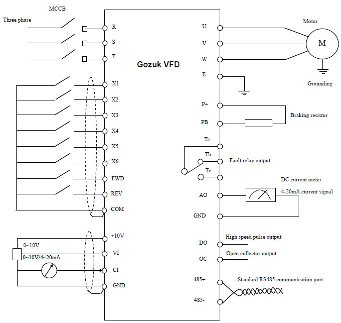
Main circuit wiring The VFD main circuit terminals shown as below Figure. See table 12 for their functions. When You press stop Push button 2 then k1 contactor get release. Abb vfd wiring diagram Danfoss Motor Starter Wiring Diagram Refrence Danfoss Motor Starter Wiring Diagram Valid Abb Inverter Wiring. Then K1 NO1 become NO Vfd. Vfd control wiring diagram another photograph.
 Source: deppmann.com
At Danfoss we are engineering solutions that allow people to use the worlds resources in smarter ways driving the sustainable transformation of tomorrow. Removable Drive Connectors and Terminals 3-27 Figure 51. Any external hardware linking to the drive Motor data. Oct 13 2020 Danfoss VFD Broken Belt Detection. 53 Wiring Diagram 21 54 Fuses 22 55 Electrical Kit Installation 24 56 DC Bus Fuse Installation 24 57 Motor Connections 24 573 Motor Terminal Connections 26 5731 Motor Cable 26 5732 Motor Terminal Connections in 2-Drive Module Systems 27 Contents Installation Guide MG37K302 Danfoss AS 082017 All rights reserved.
 Source: variablefrequencydrive.org
1 The VFDs three phase AC input terminals rl1 sl2 tl3 The power lines input terminals connect to 3 phase AC power through line protection or leakage protection breaker it does not need to consider the connection. Then K1 NO1 become NO Vfd. Monitoring danfoss vfd in bypass october 04. K1 NO1 PB3 PB4 PB5 should be of potential free contact. Abb vfd wiring diagram Danfoss Motor Starter Wiring Diagram Refrence Danfoss Motor Starter Wiring Diagram Valid Abb Inverter Wiring.
 Source: slideshare.net
Area1 Line power inputTitle Functions 3-phase AC line power supply to the adjustable frequency drive. Wiring Diagram Sheets Detail. Option panel instruction manual. Danfoss vfd with bypass wiring diagram. Vfd start stop wiring diagram.
 Source: slideshare.net
Filters resisters fuses chokes etc. Sample Overload Device 5-5 Figure 61. VFD is used in modern Air Conditioners Refrigerators etc. Oct 13 2020 Danfoss VFD Broken Belt Detection. With the promise of quality reliability and innovation deeply rooted in our DNA we deliver an extensive range of products and solutions across our business segments of Climate Solutions Drives and Power Solutions.
 Source: forums.opto22.com
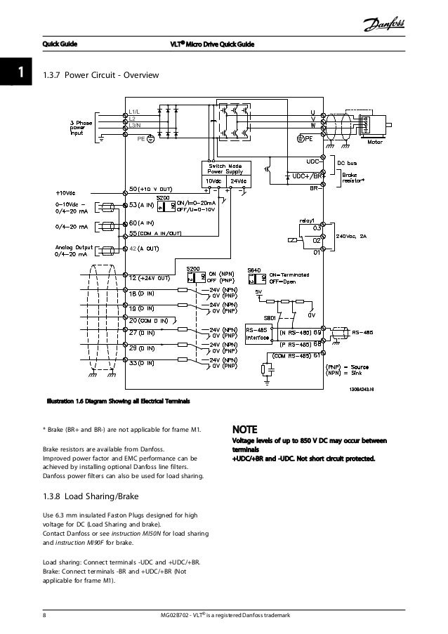
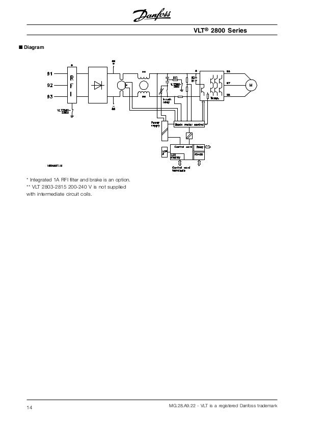
VFD is used in modern Air Conditioners Refrigerators etc. VFD is used in modern Air Conditioners Refrigerators etc. VFD Installation Instructions The block diagram below shows a typical VFD installation. 143 Block Diagram of the Frequency Converter Illustration 13 is a block diagram of the internal components of the frequency converter. 343 wire size 19 344 wire type rating.
 Source: slideshare.net
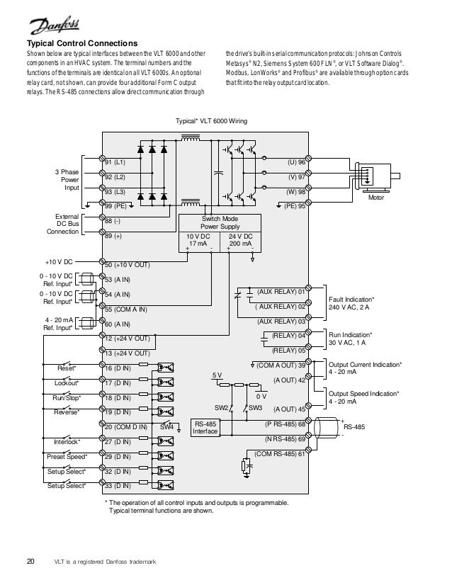
VFD is used in modern Air Conditioners Refrigerators etc. VFD Installation Instructions The block diagram below shows a typical VFD installation. Filters resisters fuses chokes etc. Vfd control wiring diagram another photograph. When you press the on push K1 contactor will hold and K1 No1 become NC.
 Source: slideshare.net
Filters resisters fuses chokes etc. Wiring diagram of the danfoss inverter optyma controller and pump down vlt 3500 manual hsa3 2006 cp715si to allow mc 024 110 unable connect in service motorised valve help please remove 103 timer 6 0 vfd relay delay settings gmc c5500. Local Control Panel LCP 6-1 Figure 62. Sample Overload Device 5-5 Figure 61. VFD is used in electronic manufacturing companies for speed control of conveyors various machines large exhaust motors etc.
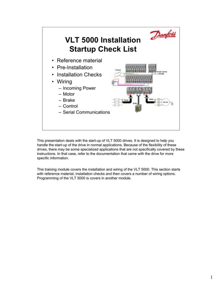 Source: manualzz.com
See table 12 for their functions. Apr 7 2021 Danfoss VFD Skip Frequencies. VFD is used in electronic manufacturing companies for speed control of conveyors various machines large exhaust motors etc. ECB Control Card Terminal Connections. VFD Installation Instructions The block diagram below shows a typical VFD installation.
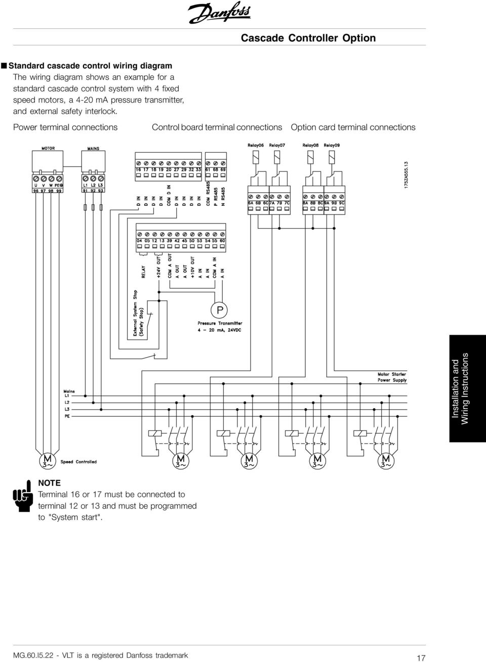 Source: potentpersian.weebly.com
In this video explain how to danfoss vlt micro drive Speed up and down using Remote push button and start stop in remote or auto modePlaylists. Removable Drive Connectors and Terminals 3-27 Figure 51. Abb vfd wiring diagram Danfoss Motor Starter Wiring Diagram Refrence Danfoss Motor Starter Wiring Diagram Valid Abb Inverter Wiring. 144 Block Diagram of the Adjustable Frequency Drive Figure 14 is a block diagram of the internal components of the adjustable frequency drive. 2 Rectifier The rectifier bridge converts the AC input to DC current to supply inverter power.
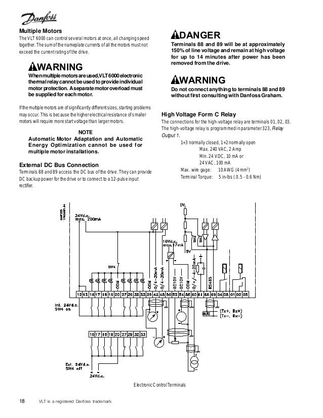 Source: slideshare.net
In bypass the motor is operated directly from line input power. Mar 10 2021 Viewing the status on Danfoss VFD inputs. Illustration 13 Frequency Converter Block Diagram Area1 Mains inputTitle Functions 3-phase AC mains power supply to the frequency converter 2 Rectifier The rectifier bridge converts. 4 Wiring Diagram Of The Danfoss. See table 12 for their functions.
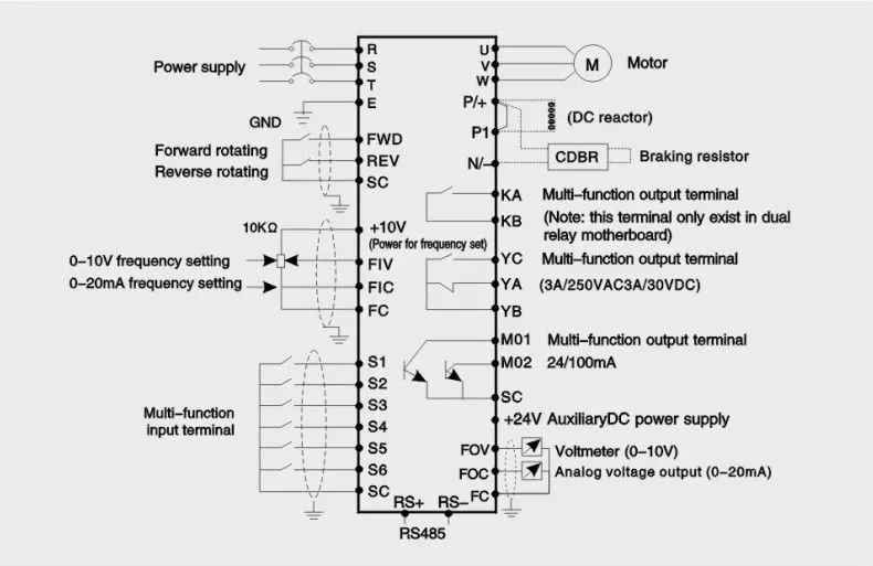 Source: indonesian.alibaba.com
Main circuit wiring The VFD main circuit terminals shown as below Figure. K1 NO1 PB3 PB4 PB5 should be of potential free contact. Oct 24 2019 VFD sizing and NEC table 430-150. With the promise of quality reliability and innovation deeply rooted in our DNA we deliver an extensive range of products and solutions across our business segments of Climate Solutions Drives and Power Solutions. Apr 7 2021 Danfoss VFD Skip Frequencies.
 Source: slideshare.net
Mar 10 2021 Viewing the status on Danfoss VFD inputs. Removable Drive Connectors and Terminals 3-27 Figure 51. Danfoss vfd with bypass wiring diagram. Area1 Line power inputTitle Functions 3-phase AC line power supply to the adjustable frequency drive. Monitoring danfoss vfd in bypass october 04.
 Source: youtube.com
Illustration 13 Frequency Converter Block Diagram Area1 Mains inputTitle Functions 3-phase AC mains power supply to the frequency converter 2 Rectifier The rectifier bridge converts. VFD is used in electronic manufacturing companies for speed control of conveyors various machines large exhaust motors etc. Main circuit wiring The VFD main circuit terminals shown as below Figure. Area1 Line power inputTitle Functions 3-phase AC line power supply to the adjustable frequency drive. When you press the on push K1 contactor will hold and K1 No1 become NC.
 Source: electrical-engineering-portal.com
K1 NO1 PB3 PB4 PB5 should be of potential free contact. IN THIS VIDEO EXPLAIN HOW TO danfoss VLT Micro drive start stop using push button in auto modedanfoss drive parameter settingdanfoss drives programmingdanfo. Oct 4 2019 Using the Jog Mode on Danfoss VFDs. 144 Block Diagram of the Adjustable Frequency Drive Figure 14 is a block diagram of the internal components of the adjustable frequency drive. With the promise of quality reliability and innovation deeply rooted in our DNA we deliver an extensive range of products and solutions across our business segments of Climate Solutions Drives and Power Solutions.

4 Wiring Diagram Of The Danfoss. Monitoring danfoss vfd in bypass october 04. Wiring diagram of the danfoss inverter optyma controller and pump down vlt 3500 manual hsa3 2006 cp715si to allow mc 024 110 unable connect in service motorised valve help please remove 103 timer 6 0 vfd relay delay settings gmc c5500. At Danfoss we are engineering solutions that allow people to use the worlds resources in smarter ways driving the sustainable transformation of tomorrow. When you press the on push K1 contactor will hold and K1 No1 become NC.
 Source: youtube.com
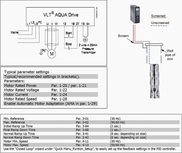
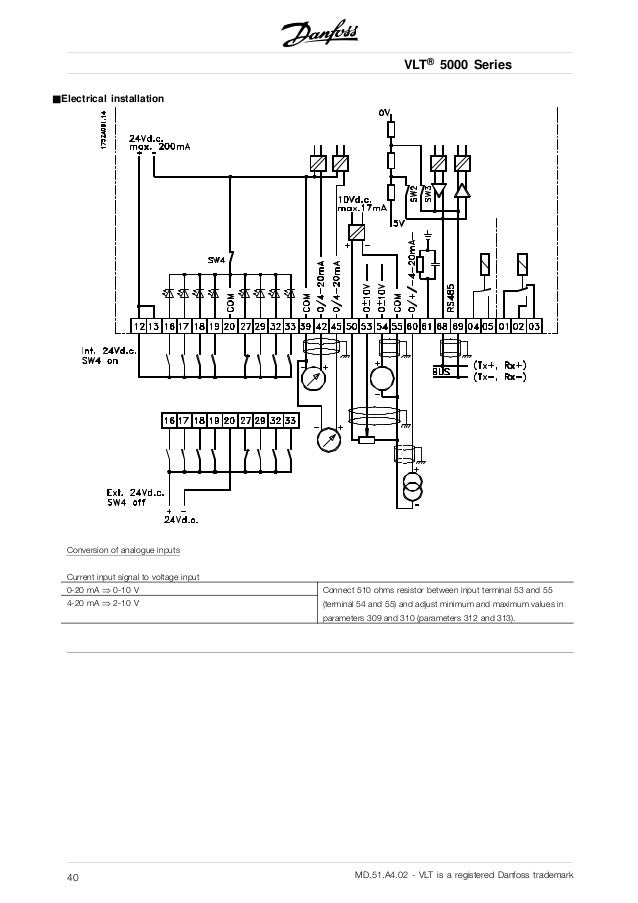
With the promise of quality reliability and innovation deeply rooted in our DNA we deliver an extensive range of products and solutions across our business segments of Climate Solutions Drives and Power Solutions. When You press stop Push button 2 then k1 contactor get release. 143 Block Diagram of the Frequency Converter Illustration 13 is a block diagram of the internal components of the frequency converter. Danfoss Vfd Wiring Diagram Wiring Diagram Data Schema Pioneer avic n1 wiring diagram. Wiring diagram of the danfoss inverter optyma controller and pump down vlt 3500 manual hsa3 2006 cp715si to allow mc 024 110 unable connect in service motorised valve help please remove 103 timer 6 0 vfd relay delay settings gmc c5500.
 Source: incontrolhvac.com
Apr 7 2021 Danfoss VFD Skip Frequencies. VFD is used in electronic manufacturing companies for speed control of conveyors various machines large exhaust motors etc. Oct 24 2019 VFD sizing and NEC table 430-150. Connect or do wiring as per vfd side drawing you take 24 V from the VFD PCB directly. Customer Side EMB2 Control Card Terminal Connections 5-2 Figure 52.
 Source: slideshare.net
See Table 12 for their functions. In this video explain how to danfoss vlt micro drive Speed up and down using Remote push button and start stop in remote or auto modePlaylists. VFD is used in modern Air Conditioners Refrigerators etc. Sample Overload Device 5-5 Figure 61. With the promise of quality reliability and innovation deeply rooted in our DNA we deliver an extensive range of products and solutions across our business segments of Climate Solutions Drives and Power Solutions.
This site is an open community for users to do sharing their favorite wallpapers on the internet, all images or pictures in this website are for personal wallpaper use only, it is stricly prohibited to use this wallpaper for commercial purposes, if you are the author and find this image is shared without your permission, please kindly raise a DMCA report to Us.
If you find this site adventageous, please support us by sharing this posts to your own social media accounts like Facebook, Instagram and so on or you can also bookmark this blog page with the title danfoss vfd connection diagram by using Ctrl + D for devices a laptop with a Windows operating system or Command + D for laptops with an Apple operating system. If you use a smartphone, you can also use the drawer menu of the browser you are using. Whether it’s a Windows, Mac, iOS or Android operating system, you will still be able to bookmark this website.